Choosing the right Injection Molding Equipment begins with the part, not the machine brochure. A thin-walled housing and a thick, ribbed component can demand very different injection speeds, pressures, and cooling times. Even a small detail, such as a side-action feature, may affect mold layout and machine compatibility. Small details matter.
A practical selection starts with the resin, part dimensions, projected area, and expected production volume. Compare clamp force and shot capacity with the mold’s requirements, then check tie-bar spacing, platen size, and mold-thickness range. These figures help prevent a costly mismatch. They do not tell the whole story. Screw design, process control, energy use, maintenance access, and local service support also shape daily performance. A machine that meets the cycle target on paper may be frustrating to operate if changeovers are difficult or spare parts take weeks to arrive.
This guide outlines how to assess equipment against real production needs, including material behavior, mold fit, output goals, and future flexibility. It also considers the trade-offs between hydraulic, electric, and hybrid machines without treating one type as universally best. There is no perfect machine for every shop. Estimates can be wrong, especially before testing a mold or confirming a material’s processing window. Careful calculations, supplier data, and, where possible, a production trial can reduce uncertainty. The aim is a well-matched machine—not simply the largest or newest one.
Start with the part, not the machine. Record its dimensions, projected area, wall thickness, tolerances, and finished weight. Then identify the resin and check its melt-flow behavior, drying needs, and recommended processing window. These details influence injection pressure, shot capacity, clamp force, and temperature control. Small details matter. A machine that can produce the required shot may still be unsuitable if its tie-bar spacing cannot fit the mold. Projected area and cavity pressure help estimate clamp force, but confirm the calculation with a qualified mold or machine engineer.
Production needs narrow the choice further. Estimate annual demand, batch size, target cycle time, changeover frequency, and acceptable downtime. High-volume work may justify automation and a faster cycle; varied, smaller runs may need easier mold changes and flexible controls. Plastics Europe’s Plastics—The Fast Facts 2024 reports 413.8 million tonnes of global plastics production in 2023. That figure covers plastics overall, not injection molding alone, but it shows the scale of material processing behind today’s supply chains. Build a practical requirement sheet before comparing machines. I would also leave room for uncertainty: actual cycle time can shift with cooling, part geometry, and resin behavior. A spreadsheet estimate is useful, but it is not a production trial.
Comparing injection molding machine types starts with the part, not the catalog. Hydraulic machines offer strong clamping force and can suit large molds or demanding applications. All-electric machines provide precise movement and repeatable control, which helps with small parts and tight tolerances. Hybrid designs combine hydraulic clamping with electric drive systems. They can balance force, precision, and energy use, but the result depends on the actual configuration.
Look beyond the machine’s headline tonnage. Check shot capacity against the part and runner, then confirm that the mold fits between the tie bars and within the platen dimensions. A mold may meet the tonnage requirement and still be too wide. Pay attention to injection speed, screw diameter, and control options as well. For a thin-walled part, filling speed may matter more than extra clamp force. For a larger component, stable clamping and sufficient shot capacity may matter more.
Configuration choices affect daily work. A suitable controller, mold-temperature connections, and space for automation can reduce setup friction. Ask operators to review the intended mold and process, not just the machine specification sheet. Real production conditions are messier than a comparison table. A lower-energy machine may not be the best fit if its cycle time or maintenance needs undermine the production plan. Test the assumptions with the mold whenever possible. That step is easy to overlook.
How to Choose the Right Injection Molding Equipment?
Calculate Clamping Force, Shot Size, and Machine Capacity
Machine selection begins with the mold’s projected area, not just the part’s weight. Estimate clamping force by multiplying projected area by cavity pressure, using consistent units. Include every cavity and the runner system. Then add an appropriate process margin, since pressure varies with material, flow length, and mold design. Too little force can cause flash along the parting line. Too much may increase tool stress. PlasticsEurope’s Plastics—The Fast Facts 2024 reports global plastics production of 413.8 million tonnes in 2023, a reminder of the scale and variety of materials processors must accommodate. That figure does not determine machine size; the resin and mold do.
For shot size, add the part and runner weights, then check the result against the machine’s rated capacity for the specific resin. A 20–80% use range is a common screening guideline, not a guarantee; confirm it against the equipment supplier’s limits and the material’s processing window. Leave room for stable metering. Also check tie-bar spacing, mold thickness, opening stroke, and injection pressure. The mold must physically fit. A paper calculation can look perfect and still miss the tie bars. One estimate may be wrong. Run a mold trial, inspect short shots and flash, and adjust only after reviewing actual cycle data.
Estimated clamping force versus selected machine capacity for three example molding jobs
How to read the chart: Required clamping force is estimated as projected area × cavity pressure × 1.2 safety factor, then converted to metric ton-force. Projected area means the part’s total projected area, including all cavities and runners.
The example jobs have shot weights of 80 g, 180 g, and 320 g, paired with machine shot capacities of 120 g, 300 g, and 500 g respectively (about 67%, 60%, and 64% utilization). These are illustrative screening values: verify actual part and runner weight, resin behavior, pressure, machine specifications, and the manufacturer’s recommended shot-capacity range before selecting equipment.
Choosing injection molding equipment starts with the mold, not the machine’s headline tonnage. Check the mold’s dimensions against the platen, tie-bar spacing, and opening stroke. Confirm that the machine can provide enough clamping force for the projected area and cavity pressure. Small mismatches matter. A mold may fit on paper but leave too little room for safe installation or cooling-line connections.
Material compatibility affects the screw, barrel, and process window. Compare the resin’s recommended melt temperature and viscosity with the machine’s heating capacity and shot-size range. A shot that uses only a small fraction of the barrel can increase residence time and risk material degradation. For moisture-sensitive resin, specify a dryer that can maintain the required temperature and dew point. Check the interfaces. Hoses, fittings, and controls must connect cleanly.
Auxiliary equipment should support the whole cycle, not just one machine setting. Size the chiller for the mold’s heat load, and match the temperature controller to the mold’s channels and operating range. Verify electrical supply, floor space, and communication signals before delivery. A spec sheet can still mislead when it omits a particular mold feature or material grade. If key details are uncertain, confirm them with the mold and material suppliers, then run a controlled trial. The first selection may not be perfect; document cycle time, part quality, and temperature stability, and adjust from measured results.
| Selection Dimension | What to Check | Material Compatibility | Mold Compatibility | Auxiliary Equipment | Practical Selection Guidance |
|---|---|---|---|---|---|
| Clamping force | Projected area of all cavities and runners; estimated cavity pressure; machine clamp capacity. | Materials with higher processing pressures or long flow paths may require more clamping force. | Include the projected area of the complete molded shot, not just one part. | Not usually a separate auxiliary system; confirm the machine’s rated force and control range. | Estimate force from projected area multiplied by cavity pressure, then apply an appropriate safety margin based on the part and process. Confirm the calculation with the mold and machine suppliers. |
| Shot capacity and injection unit | Part-and-runner shot weight, screw diameter, injection pressure, and available plasticizing capacity. | Check melt-temperature range, viscosity, shear sensitivity, and whether the resin requires a wear-resistant screw or barrel. | Account for the complete shot, including runners and cold slugs where applicable. | A resin dryer or material conveying system may be needed depending on resin and production conditions. | Choose an injection unit that can fill the mold at the required pressure and process the shot consistently. Compare usable capacity with the actual shot size using the machine manufacturer’s guidance. |
| Mold dimensions and tie-bar spacing | Platen dimensions, tie-bar spacing, mold width and height, mold thickness, and mounting pattern. | Consider any material-specific mold-temperature or corrosion concerns when specifying mold construction and surface treatment. | Verify that the mold fits between the tie bars and can be safely mounted on the platens. | Allow space for hoses, connectors, hot-runner wiring, and mold-temperature-control lines. | Check the machine’s mold installation drawing and permitted mold-thickness range before ordering or transferring a mold. |
| Mold opening and ejection | Required opening stroke, daylight, ejection stroke, ejector force, and ejection method. | Part shrinkage and flexibility influence release behavior and ejection needs. | Confirm that the part can clear the mold and that ejector locations align with the machine’s ejector system. | Robots or take-out equipment may need additional clearance and an appropriate interface. | Check the molded part’s depth and handling path against the machine’s opening and ejection limits. Include any required robot access in the layout. |
| Resin drying and material handling | Resin moisture requirements, material consumption, hopper capacity, and feed consistency. | Many hygroscopic resins, such as polycarbonate, polyamide, and PET, commonly require drying; exact conditions depend on the grade and supplier instructions. | Stable material preparation helps maintain consistent filling, appearance, and part properties. | Use a desiccant dryer or other suitable drying system when required; consider a loader, hopper, and conveying lines for production supply. | Follow the resin supplier’s drying temperature, time, and moisture target. Avoid assuming that every grade of a resin family has identical drying requirements. |
| Melt temperature and plasticizing | Barrel temperature zones, screw recovery time, back pressure, and residence time. | Match the machine’s processing range to the resin grade. Heat-sensitive materials need controlled residence time and temperature. | Gate size and runner design affect filling behavior and can influence the required injection profile. | A gravimetric blender may be useful when precise mixing of colorants, regrind, or additives is required. | Confirm that the injection unit can melt and meter the material at the planned cycle rate without excessive residence time or degradation. |
| Mold temperature and cooling | Required mold temperature, cooling-channel layout, circuit flow, and temperature stability. | Different polymers and grades have different mold-temperature ranges and cooling behavior; consult the resin processing guide. | Check the number and layout of cooling circuits, connector type, and expected heat load. | Select a mold temperature controller, chiller, or cooling-tower circuit to suit the required temperature and heat removal. | Size the cooling system for the mold’s heat load and required stability. Verify that each circuit has adequate flow and that supply and return temperatures are monitored. |
| Hot runner and temperature control | Hot-runner voltage, zones, connector arrangement, heater load, and thermocouple type. | Confirm that the material’s processing window is compatible with the hot-runner design and temperature-control capability. | Match the controller capacity and connections to the mold’s specified hot-runner zones. | Use a compatible hot-runner temperature controller and suitable electrical connections. | Check the mold wiring diagram and controller specifications before installation. Cold-runner molds do not require hot-runner controllers. |
| Venting and gas management | Parting-line vents, vent depth and location, and risk of trapped air or burns. | Material viscosity and filling speed affect how easily air is displaced and how sensitive the process is to trapped gas. | Ensure the mold has suitable venting and that vents can be maintained without damaging the sealing surfaces. | Vacuum venting may be considered for applications where mold design and process requirements justify it. | Review venting with the mold designer, especially for long flow paths, deep ribs, or end-of-fill areas. Do not use vacuum equipment as a substitute for appropriate mold venting. |
| Automation and part handling | Cycle time, part release, robot reach, safety guarding, and machine communication interfaces. | Part temperature and stiffness at ejection affect whether parts can be picked, stacked, or conveyed reliably. | Consider core pulls, unscrewing mechanisms, and the space needed for safe mold access. | Possible equipment includes a robot, conveyor, part separator, and scrap or runner collection system. | Specify the automation package together with the mold layout and machine interface requirements. Confirm cycle-time targets and safety requirements for the complete cell. |
| Utilities and installation | Electrical supply, cooling-water capacity, compressed air, floor space, lifting access, and safety requirements. | Material preparation may add electrical, ventilation, or conveying needs. | Allow for mold-change access, lifting points, connections, and service clearance. | Include the utility demand of dryers, temperature controllers, chillers, loaders, and robots. | Check total utility requirements and machine installation drawings before delivery. Ensure that all auxiliary equipment can operate within the available site capacity. |
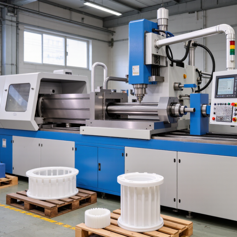
Choosing injection molding equipment starts with the part, not the machine’s advertised tonnage. Check clamp force, shot size, and platen dimensions against your actual molds. Then test the controls during a setup. Can operators adjust pressure profiles, save recipes, and understand alarms without hunting through menus? A steady process matters more than a polished screen. Energy use adds up across every shift, so compare motor and heating demands using your expected cycle times and production mix. Ask for measured data where possible; estimates can miss real operating conditions.
Safety and lifecycle costs deserve equal attention. Look for clear guarding, accessible emergency stops, and maintenance points that do not require awkward reach. Ask a qualified technician to review installation needs and service intervals. One detail is easy to overlook: a lower purchase price may mean longer setup times or harder-to-source components. Estimate costs over several years, including training, maintenance, downtime, and likely production changes. The forecast will not be perfect. Revisit it when your product mix changes.
Tips: Bring a representative mold and resin specification to equipment trials. Record cycle time, energy readings, setup steps, and alarm responses. Compare notes with operators and maintenance staff; their feedback often reveals practical issues a quote cannot show.